Solidworks Strain Relief Sheet Metal

Auto Vs Corner Relief In Solidworks Sheet Metal

Managing Your Favorite Materials Using Materials Library In Solidworks

Sheet Metal Tutorial 2 How To Work With Sheet Metal In Autodesk Fusion 360 Sheet Metal Autodesk Tutorial

Solidworks Sheet Metal Tutorial Forming Tool Youtube Solidworks Tutorial Solidworks Sheet Metal

Solidworks Sheet Metal Lofted Bend Youtube Sheet Metal Drawing Solidworks Sheet Metal

Solidworks Sheet Metal Exercise Youtube Sheet Metal Drawing Sheet Metal Solidworks
If i have a 30mm gap and i want a flange tab with a relief of 1mm my flange should be 28mm leaving 1mm each side of the flange.
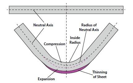
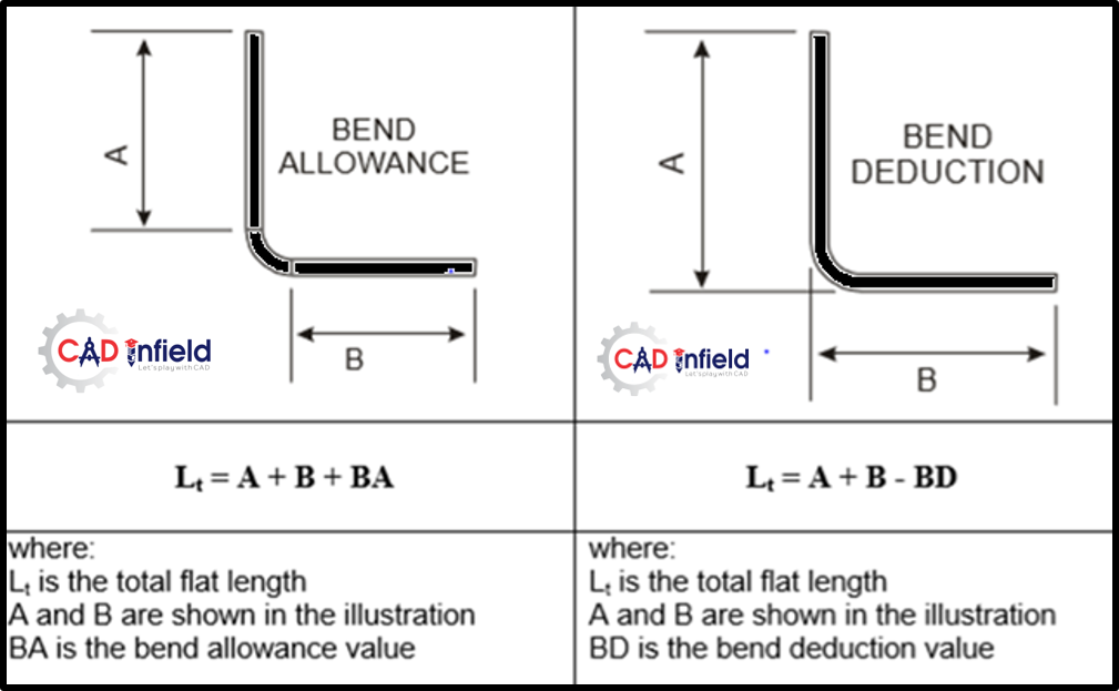
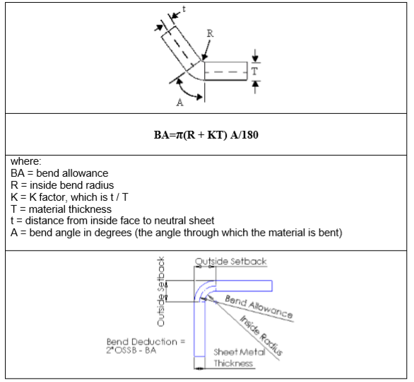
Solidworks strain relief sheet metal. A bent sheet metal part is created whose dimensions in the flattened state reflect the specified bend allowance and radius values. In the corner relief propertymanager under scope select the sheet metal body to which to apply the corner relief. Welcome to solidworks simulation help. The distance d is determined by the following equation.
The options and values you specify for bend radius bend allowance and auto relief are shown as the default settings for the next new sheet metal part that you create. You can add a corner relief to a single sheet metal body. K factor most of these factors vary from shop to shop and equipment to equipment so normally each shop sets up their own sheet metal calculations. Lists corners to which you can apply corner relief.
Click corner relief sheet metal toolbar or insert sheet metal corner relief. Select keep body if you want to keep the solid body to use in another convert to sheet metal feature. The relief gap should be across the full length of the flange. Set the sheet thickness and default bend radius.
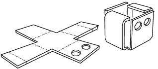
The distance d represents the width of the rectangular or obround relief cut and the depth by which the side of the rectangular or obround relief cut extends past the bend region. Sheet metal functionality within solidworks provides designers with powerful tools to create accurate formable models of their designs. You can add a corner relief to a single sheet metal body. Lets you select the sheet metal body to which the corner relief is applied.
When you select a corner it is highlighted in the graphics area. Solidworks welcomes your feedback concerning the presentation accuracy and thoroughness of the documentation. Accessing and using help. When cleared the body is consumed by the convert to sheet metal feature.
Click corner relief sheet metal toolbar or insert sheet metal corner relief. However a common point of confusion when using sheet metal functions is the difference between the auto relief and corner treatment tools. In real life manufacturing you cannot cut anything without losing some material. In the corner relief propertymanager under corner type select a two or three bend corner.
Solidworks 2019 sp05 to disable web help from within solidworks and use local help instead click help use solidworks web help. Strain is a dimensionless quantity. Select a face as the fixed face for the sheet metal part. Under corners click collect all corners to list all corners in the sheet metal body.
Under scope select the sheet metal body to which to apply the corner relief. D relief ratio part thickness the bend region is represented by the dark gray area of the diagram. Solidworks keeps the bend thickness consistant with the sheet metal gage. Under corners click collect all corners to list all corners in the sheet metal body.

Pin On Solidworks

Pin On Cam

Solidworks Sheet Metal 2d To 3d Sheet Metal Drawing Solidworks Tutorial Sheet Metal

Solidworks Sheet Metal Tutorial Forming Tool Youtube Solidworks Solidworks Tutorial Sheet Metal Drawing
Analyzing The K Factor In Sheet Metal Bending

Video Tech Tip Working With The Corner Relief Option Within Solidworks Sheet Metal Youtube

Bend Order In Solidworks Sheet Metal Parts Solidworks Sheet Metal Solid Works
Sheet Metal Fabrication Fundamental Cad Infield Fabrication Design

Fab Drawing Simple Sheetmetal Part Drawings Graphic Solidworks

How To Work With Auto Relief Trim Solidworks Tutorials Sheet Metal Youtube

Oblique Cylinder Sheet Metal Pattern Development Youtube

New Tendency Click Shelf Steel Furniture Design Metal Sheet Design Sheet Metal
Bending Basics The Hows And Whys Of Springback And Springforward

How To Design A Car Wheel Rim On Autodesk Fusion 360 Fusion 360 Tutorial For Beginners Car Wheels Rims Wheel Rims Car Wheel

Pin On Moje Wedkowanie

Construction Set For Sheet Metal Scale Model Making Sheet Metal Drawing Sheet Metal Metal Tree Wall Art

Solidworks Tutorial Sketch Sheet Metal Screw In Solidworks Youtube Solidworks Tutorial Solidworks Sheet Metal
1
Design For Manufacture And Assembly

Press Brake Bending Basics A Guide To Sheet Metal Bending Machinemfg

Base Flange Tab Command Sheet Metal Tutorial Youtube
Https Dl Zwsoft Com Zw3d Pc Zw3d Marketing White Paper Zw3d White Paper Sheet Metal Design Pdf

Bending Metalworking Wikipedia
Design To Fabricate Introduction By Narayanpure Aatmling Medium

Inventor 101 Sheet Metal Basics Autodesk Virtual Academy Youtube

Tevo Tornado Reviews Upgrades And More 3d Printing For Gaming And More 3d Printing Tornado 3d Printing News
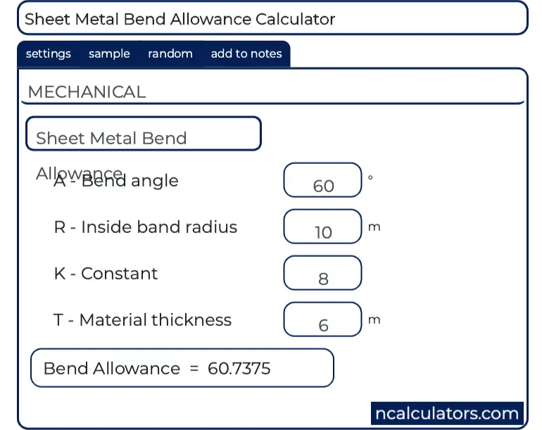
Sheet Metal Bend Allowance Calculator

Fastest Ever Xi Mtower Pcie

Solidworks Basic Tutorial 16 How To Make Spanner In Solidworks Must Watch Youtube

Aluminium Sheetmetal Bending Forming Product Material Aluminum Alloy Sheet Thickness 1 5mm Siz Aluminum Sheet Metal Sheet Metal Fabrication Metal Bending
What S New Fusion 360 Blog

Solidworks Tutorial Design Of Tank Youtube In 2020 Solidworks Tutorial Mechanical Design Solidworks
Https Cdn2 Hubspot Net Hubfs 340051 Design Guides Xometry Designguide Sheetmetal Pdf

Zusammenbau Und Details Maschinenzeichnung Pdf Mechanical Engineering Design Mechanical Design Mechanical Engineering Projects

Abaqus Sheet Metal Bending Part 1 Youtube

7 Must Follow Sheet Metal Design Guidelines To Strengthen Your Design

Assembly And Details Machine Drawing Pdf Mechanical Engineering Design Mechanical Design 3d Drawings
Custom Sheet Metal Fabricating

When Laser Meets Tubing Metal Metal Fabrication Trumpf

Planet Solidworks

Solidworks Simulation An Overview Sciencedirect Topics

