Steel Roof Diaphragm Design Example
Structure Magazine Steel Deck Diaphragm Design 101

Design Of Steel Deck Diaphragms Youtube

How To Install Roof Decking In Diaphragm Tata Steel
Https Www Pdhlibrary Com Sites Default Files 0007188 Steel 20roof 20deck 20diaphragms 20on 20cfs 20framing Pdf
Http Www Sdi Org Wp Content Uploads 2013 04 Pmddda Pdf
Https Cssbi Ca Assets Resources Design Manuals Cssbi B 13 06 Pdf Pdf
Main features roof diaphragm design example.
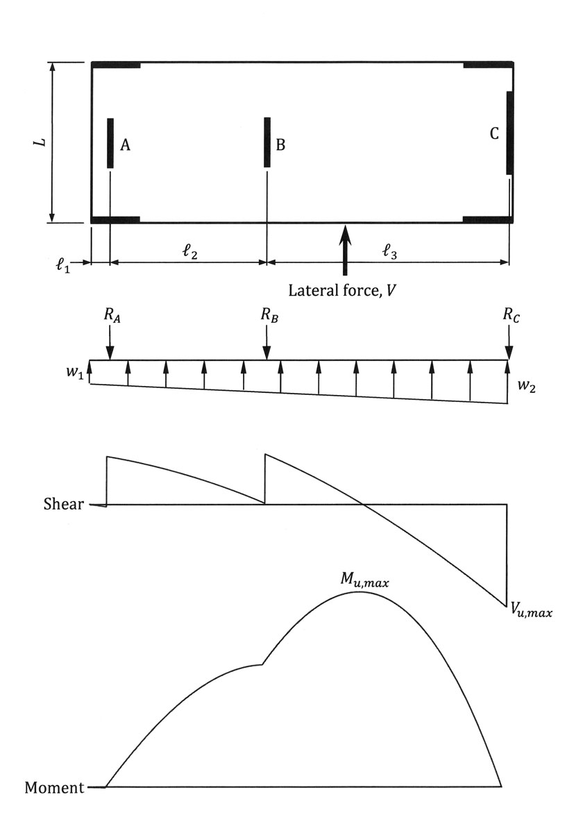
Steel roof diaphragm design example. A roof design gives the chance to extra floor space in the roof volume similar to a space or upper room space. Themaximum end reaction r of the roof diaphragm therefore is ww wl x l 2. Now let s work on an example. The actual behavior may more closely resemble a continuous beam with intermediate supports.
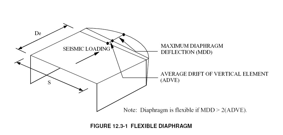
Design a roof deck for a length of l 500 ft. It should be noted that the flexible diaphragm presented in the example is a conservative approach as it assumes two simple spans. For the roof in this example the total uniform load on the diaphragm equals the combined effects of the windward and leeward cladding reactions ww wl. The roof diaphragm design example can go up against different style that when nitty gritty right can ooze a cutting edge feel.
The roof deck is supported by joists that are thick and spaced at 5 ft. Design the diaphragm for wind loading using allowable stress design method. The roof deck is a wr wide rib type panel with a panel width of 36. Astm a36 fy 36 ksi for structural steel astm a615 gr 40 for 3 4 gr 60 for 5 and larger rebar.
R divided by length b equals the collector. The sdi diaphragm design manual third edition is an excellent design reference every engineer should utilize if designing with steel deck diaphragms. First off the roof diaphragm design example is an extremely basic direct and utilitarian design every single current trademark. Design criteria and specifications a.
2003 international building code. See the attached examples and video to really help better understand general diaphragm design better. A concrete floor is relatively rigid compared to steel moment frames whereas a metal deck roof is relatively flexible compared to concrete or. The manual includes pertinent design information considerations fastener information deck shear capacity tables and a plethora of highly relevant design examples stepping you through all the.
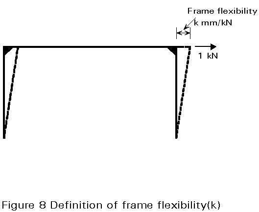
The sdi diaphragm design manual third edition is an excellent design reference every engineer should utilize if designing with steel deck diaphragms. Timber beam design seismic forces wind forces floor shearwall diagram lateral loads roof diaphragm design shearwall design continuous footing design. Design rigidity means relative rigidity.
What Is Diaphragm Design Why Is It Important

Inelastic Response Of Steel Roof Deck Diaphragms With Nailed And Welded Connections Sciencedirect

Example Calculating Semirigid Diaphragm E Ram Staad Opentower Wiki Ram Staad Opentower Bentley Communities
Flexible Or Rigid Multi Story Light Frame Structure Design Considerations Simpson Strong Tie Structural Engineering Blog
Design Examples For Steel Deck Diaphragm Calculator Web App Simpson Strong Tie Structural Engineering Blog

Diaphragm Design With Steel Deck Steel Joist Institute
Structure Magazine Design Of Reinforced Concrete Diaphragms For Wind
Https Scholarsmine Mst Edu Cgi Viewcontent Cgi Article 1012 Context Ccfss Sdi
Previous Next Contents

Standing Seam Metal Roof On A Bar Joist Roof Structural Engineering General Discussion Eng Tips
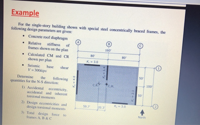
Example For The Single Story Building Shown With S Chegg Com
Https Www Aisc Org Globalassets Modern Steel Archives 2018 05 Developingdiaphragmanalysis Pdf
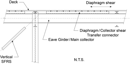
Seismic Corner Diaphragm Collector Shear Transfer Cisc Icca
Structure Magazine 5 Over 2 Podium Design

Structural Steel Framing Metals Download Free Cad Drawings Autocad Blocks And Cad Details Arcat

Manuals And Handbooks Steel Deck Institute

Seismic Design Forces On Concrete Masonry Buildings Ncma
Metal Buildings 101 The Basics Of Metal Building Systems Construction
Https Encrypted Tbn0 Gstatic Com Images Q Tbn 3aand9gcq6cjpwunyab Acacevbeyf6goxktjwhukprz26j6p Gbqv1bzv Usqp Cau
Http Scholarsmine Mst Edu Cgi Viewcontent Cgi Article 1901 Context Isccss
Warehouse Diaphgragm Expansion Joint Chord Continuity Structural Engineering General Discussion Eng Tips
Open Front Structure Rigid Diaphragm Structural Engineering General Discussion Eng Tips

Diaphragm Slurry Wall Braced With Struts 2d Section Design Deepex

What Is A Roof Diaphragm

Design Of Composite Steel Deck Floors For Fire Steel Deck Steel Frame Construction Metal Deck
Https Www Newmill Com Pdfs Diaphragm Design Pdf

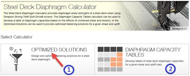
Design More With Our New Steel Deck Diaphragm Calculator App Simpson Strong Tie Structural Engineering Blog
Https Www Newmill Com Pdfs Steel Decking Intro Pdf
Https Ef Engr Utk Edu Ce576 2016 01 Notes Shear Walls 1 Pdf
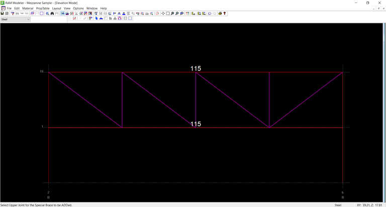
Ramss Truss Modeling And Design Tn Ram Staad Opentower Wiki Ram Staad Opentower Bentley Communities
Https Www Woodworks Org Wp Content Uploads Presentation Slides Revised Ww Cantilever Example Workshop Comments 0619 Pdf
Cold Formed Steel Framing Design Manual 2018 04 27 Building Enclosure

Structure Magazine Long Span Open Web Trusses
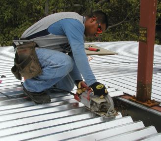
How Steel Deck Is Shaking Up Cold Formed Steel Framing Design Informed Infrastructure

Steel Deck Is A Cold Formed Corrugated Steel Sheet Canam Buildings
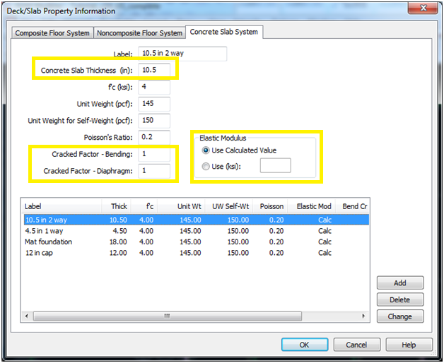
Ram Frame Semirigid Diaphragms Faq Ram Staad Opentower Wiki Ram Staad Opentower Bentley Communities
Https Www Bca Gov Sg Publications Buildabilityseries Others Structural Steel Design And Construction Lowres Pdf
Https Www Woodworks Org Wp Content Uploads Tx Wind Workshops Hour 4 Multi Story Lateral Design Pdf

Pdf Seismic Response Of Single Storey Buildings With Flexible Diaphragms

Ad 313 Precast Concrete Floors In Steel Framed Buildings Achieving Floor Diaphragm Action And Acoustic Performance Mimari Detaylar Dosemeler Mimari
Https Www Vulcraft Com Upload Vulcraft Vp1 Interactive Pdf

